

This article presents a detailed, informative, and easy-to-follow guide on converting your LM7 alternator’s wiring from a 4-pin configuration to a simplified one-cable system. Whether you are a DIY enthusiast or an automotive professional performing an LS or LM7 swap, this guide covers every aspect—from understanding the technical basics and the significance of each pin to the complete installation process and troubleshooting tips.
Introduction
Modern vehicle swaps and engine conversions often require adapting the stock alternator wiring to suit aftermarket setups. With the LM7 alternator, many users have found that converting the standard 4-pin connector into a simplified one-cable system improves reliability and reduces complexity. In this guide, we explore every detail of the lm7 4 pin to 1 cable alternator wiring diagram, explain the underlying electrical principles, and offer practical instructions to ensure you achieve a flawless installation.
Understanding the LM7 Alternator
The LM7 alternator has earned a reputation for its robustness and performance, making it a popular choice in vehicles such as the Tahoe and various LS swaps. Developed to meet the increasing demands of modern power systems, the LM7 delivers ample amperage and reliable voltage regulation.
In many LM7 applications, the alternator’s original wiring features a 4-pin connector that includes multiple functions. However, simplifying the wiring to a one-cable system can enhance performance and ease maintenance. This conversion reduces the risk of wiring errors and allows for a streamlined charging circuit that is easier to troubleshoot and upgrade.
The 4-Pin Connector Explained
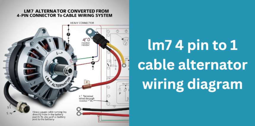
A key step in the conversion process is understanding the role of each pin in the original 4-pin connector. The four pins typically serve the following purposes:
- L (Lamp/Exciter): This pin is crucial for initiating the alternator’s charging process by providing an excitation signal.
- S (Sense): This pin monitors the system voltage to help regulate the output effectively.
- F (Field): It controls the strength of the magnetic field generated within the alternator.
- P (Pulse/Tachometer): This pin often supplies a pulse signal that can be used for engine speed monitoring or tachometer functions.
Manufacturers may use different color codes for these wires depending on the model year and specific application. A thorough understanding of these functions is essential before you begin converting the wiring to a one-cable system.
Why Convert to a “1-Cable” Wiring System?
Converting from a 4-pin to a one-cable system provides significant benefits. The process simplifies the wiring harness by focusing on the most critical functions:
- Simplified Installation: With fewer wires to connect and manage, the one-cable system reduces installation time and the potential for errors.
- Enhanced Reliability: Fewer components mean less chance for wiring faults, which can improve overall system reliability.
- Cost-Effectiveness: Reducing the number of wires and connectors often leads to lower material costs and easier long-term maintenance.
- Optimized Performance: By ensuring that the excitation circuit is properly controlled—typically through the use of a resistor—the alternator can reach its optimum charging efficiency.
Tools and Materials Required
Before beginning the conversion, it is essential to gather all necessary tools and materials. A table below outlines what you will need:
| Item | Description |
|---|---|
| LM7 Alternator (4-pin model) | The alternator you intend to convert from 4-pin wiring to a one-cable setup |
| 470-ohm Resistor | Used to limit current on the L (exciter) wire; alternative resistor values may work |
| Quality Wiring Harness | Suitable gauge cables and connectors (e.g., Metri-Pack connectors) |
| Tools | Wire strippers, crimping tool, soldering iron, multimeter, Dremel, insulation tape |
| Safety Equipment | Gloves, eye protection, and a safe work area |
Having the correct tools ensures a smooth and safe installation process.
Step-by-Step Wiring Process
Pre-Installation Preparation
Begin by carefully reviewing your vehicle’s wiring schematics and disconnecting the battery to ensure safety. It is advisable to label all existing connections before disconnecting the stock 4-pin connector, so you can identify each wire during the conversion.
Removing the Stock 4-Pin Connector
The next step involves removing the original connector from the LM7 alternator. Gently disconnect each wire and note its function based on your schematics. This process is essential because it allows you to determine which wires are critical for the one-cable system. Typically, the main charge output and the excitation (L) wire are the only ones you need to preserve.
Wiring the Main Charge Circuit
For the main charge circuit, you must run a heavy-gauge cable directly from the alternator’s battery post to the battery. This connection supplies the necessary power to charge the battery and run the vehicle’s electrical system. In many cases, this cable remains unchanged from the original setup.
Wiring the Exciter Circuit (L Terminal)
The excitation circuit is where the conversion becomes crucial. The L terminal, which normally connects to a warning lamp or dummy light, must be wired through a resistor—commonly a 470-ohm resistor—to limit current and properly excite the alternator. By controlling the current with this resistor, you prevent damage to the alternator’s regulator and ensure optimal charging voltage.
Managing Unused Pins
Once the main circuits are re-established, you will need to handle the remaining pins (S, F, and P). Depending on your vehicle’s requirements, you may choose to:
- Leave these pins disconnected,
- Tie the S (sense) wire to the battery positive to maintain voltage regulation,
- Or properly terminate them with insulation to avoid interference.
Final Connections and Testing
After securing all wiring, insulate every connection using heat shrink tubing or insulation tape. Once everything is in place, reconnect the battery and use a multimeter to verify the correct voltage and continuity across all connections. This testing phase confirms that the alternator is correctly excited and charging the battery.
Detailed Wiring Diagrams and Visual Aids
To enhance understanding, it is beneficial to include annotated diagrams and visual aids. Below is an example table summarizing the wiring connections for the simplified one-cable system:
| Connection Type | Description | Visual Aid |
|---|---|---|
| Main Charge Wire | Connects the alternator battery post directly to the battery | Diagram 1 |
| L (Exciter) Wire with Resistor | Includes a 470-ohm resistor inline to limit current on the L terminal | Diagram 2 |
| Unused Pins (S, F, P) | Safely insulated or terminated based on application needs | Diagram 3 |
High-resolution images, color-coded diagrams, and step-by-step photos or even a video tutorial can further clarify each step in the process.
Troubleshooting and Common Issues
Even with careful installation, some issues may arise. Common problems include:
- The alternator not charging due to incorrect resistor value,
- Loose connections leading to intermittent voltage drops,
- Overcharging if the unused pins are not properly managed.
If you experience any issues, use a multimeter to conduct voltage and continuity tests. Create a troubleshooting checklist that includes verifying the resistor’s integrity, ensuring that all connections are secure, and checking that the battery is receiving the correct voltage.
Frequently Asked Questions (FAQs)
Here are a few common questions that often arise regarding the lm7 4 pin to 1 cable alternator wiring diagram:
- What resistor value is typically recommended for the L terminal?
A 470-ohm resistor is standard, but slight variations may be acceptable based on your specific alternator requirements. - Can the resistor be substituted with a dummy charge lamp?
Yes, a dummy lamp can work, but the resistor is preferred for its precise current limiting properties. - How do I verify that my one-cable system is functioning correctly?
Use a multimeter to check for proper voltage output and ensure that the alternator is excited during engine operation. - Should the S (sense) wire be tied to battery positive?
In many setups, connecting the S wire to battery positive helps the regulator accurately sense the system voltage.
Conclusion
In summary, converting your LM7 alternator from a 4-pin configuration to a one-cable system using the lm7 4 pin to 1 cable alternator wiring diagram can significantly simplify your installation while enhancing performance and reliability.
By understanding each pin’s function, carefully installing a current-limiting resistor on the L terminal, and securely managing the remaining wires, you can achieve a robust, optimized charging system for your vehicle.
This guide provides a detailed roadmap—from tools and preparation to final testing—ensuring that both novices and experts can successfully complete the conversion.
With this comprehensive guide at your fingertips, you are now equipped to undertake your LM7 wiring conversion with confidence and precision. Enjoy a simplified, high-performance charging system that not only meets but exceeds your expectations!
Other Posts Like lm7 4 pin to 1 cable alternator wiring diagram
The Ultimate Guide to crewlogout: Comprehensive Analysis, History, and Implementation Strategies